OVERVIEW
THIS PRODUCT WAS DISCONTINUED MAY 2025
• EGT Probe Input: Type K Thermocouple (8 independent input channels)
• BONUS! On-board +/- 4g Accelerometer
• Linearized Analog Output: 0 to 5 VDC (9 independent output channels)
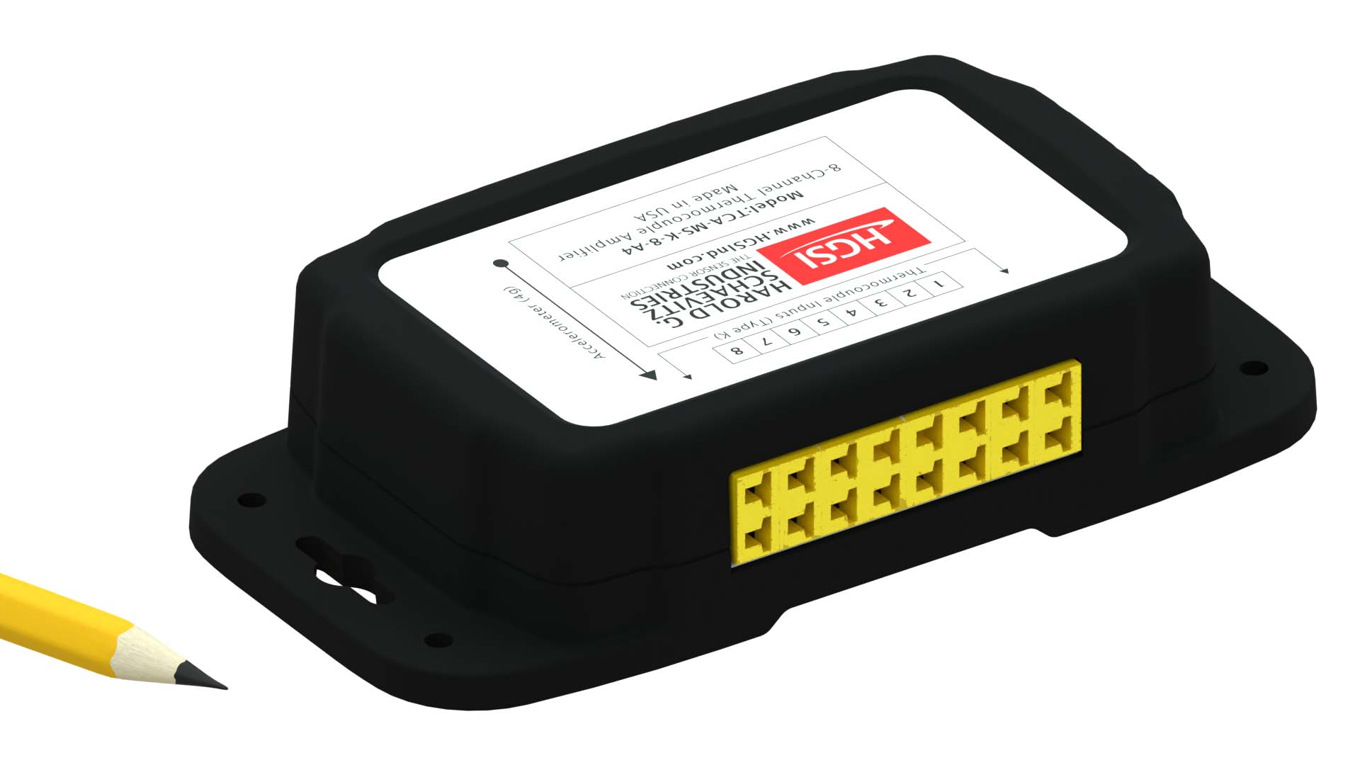
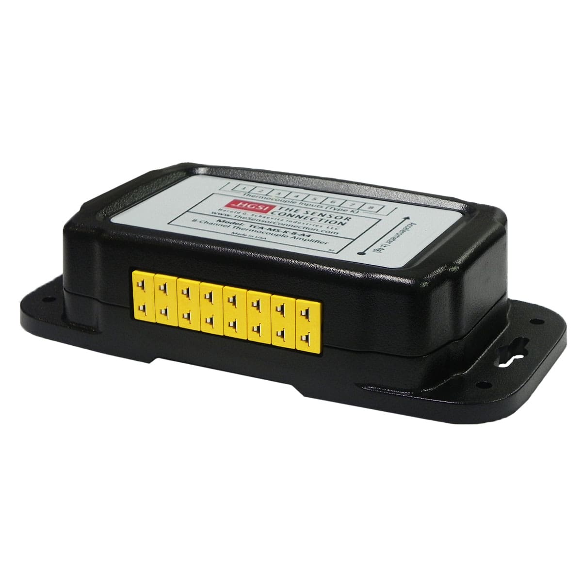
• Includes (8) mini-plug signal input connectors
• Includes detachable signal output/power wiring harness
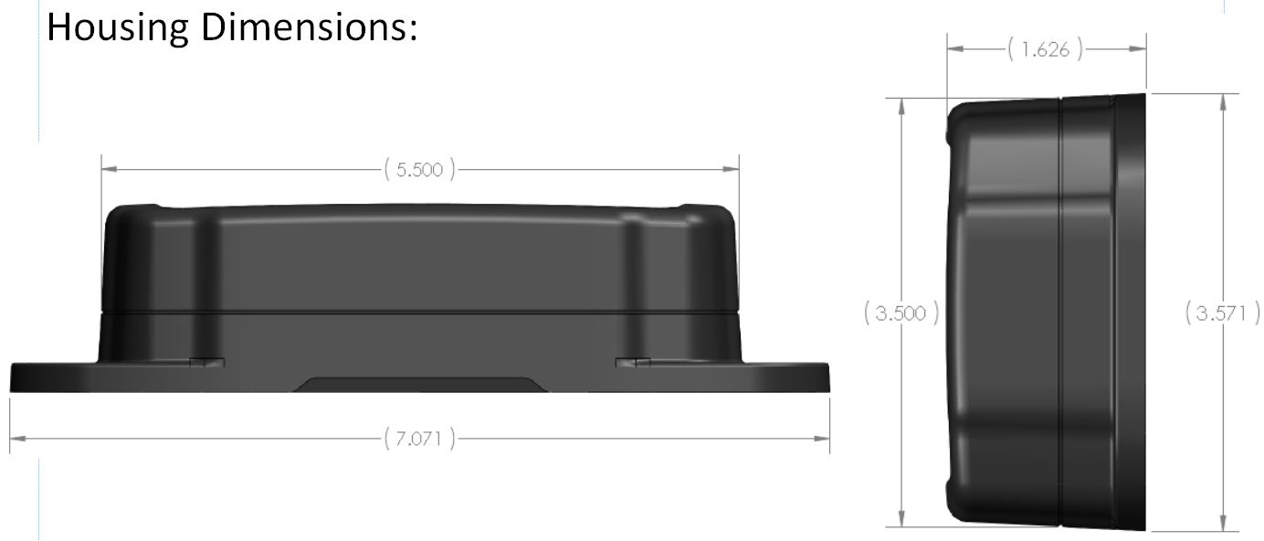
• Compact Size, only 7.0" x 3.5" x 1.6"
• Temperature Measuring Range: +32 to +2282°F (0 to +1250°C)
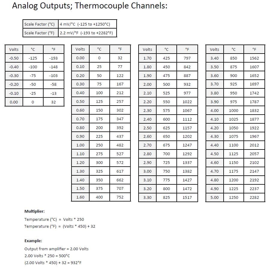
• Output Scale Factor: 2.2 mV / °F (4.0 mV / °C)
• Onboard Accelerometer Measuring Range: +/- 4g
• Output Scale Factor: 625 mV / g
Plug and Play Compatible with the Following TSC Products:
• EGT Probes - All
• CHT Sensors - All Type K
• Stick-On Probes - All Type K
• Thermocouples - All Type K
Temperature Probe not included, please purchase separately
MADE IN THE USA
The Sensor Connection TCA-MS-K-8-A4 EGT Probe Thermocouple Amplifier Module functions to convert the low output voltage signal from up to 8 Type K thermocouple EGT probes into 8 independent linearized 0 to 5 VDC output voltages. This output is ideal for interfacing to dataloggers, aftermarket ECU's, temperature indicators, chart recorders, controllers, or other motorsports instrumentation equipment.
Also includes an onboard single-axis +/- 4g capacitive accelerometer for measuring acceleration and brake events.
IMPORTANT DISCLAIMER IF YOU ARE CONSIDERING USING THIS INSTRUMENT IN AN AIRCRAFT:
This instrument is not certified by the FAA. Fitting of this instrument to certified aircraft is subject to the rules and conditions pertaining to such in your country. Please check with your local aviation authorities if in doubt. This instrument is intended for ultralight, microlight, homebuilt and experimental aircraft. Operation of this instrument is the sole responsibility of the pilot in command (PIC) of the aircraft. This person must be proficient and carry a valid and relevant pilot’s license. This person has to make themselves familiar with the operation of this instrument and the effect of any possible failure or malfunction. Under no circumstances does The Sensor Connection or manufacturer condone usage of this instrument for IFR flights.
TECHNICAL SPECIFICATIONS
Number of Inputs: | 8 |
Input: | Type K thermocouple (ungrounded) |
Input Resistance: | 60k Ω |
Max Bias Voltage on Input: | 5.8 V |
Thermocouple Measuring Range: | +32 to +2282°F (0 to +1250°C) |
Input Connection: | Mini Thermocouple Jack |
Number of Output Channels: | 9 total (8 for Thermocouple Channels, 1 for Accelerometer) |
Thermocouple Output Scale Factor (nominal): | 2.2 mV / °F (4.0 mV / °C) |
Accelerometer Output Scale Factor (nominal) | 625 mV / g |
Resolution: | Infinite |
Response Time: | > 1 mS |
Non-Linearity: | < +/- 2% FRO |
Output Cable: | 12 conductor, 22 AWG, PVC jacket, 3 foot long (detachable) |
Supply Voltage: | 10 to 32 VDC |
Current Draw: | < 50 mA |
Operating Temperature Range: | +32 to +125°F (0 to +50°C) |
Liquid & Dust Protection: | IP51 |
Housing Dimensions (L x W x H): | 7.0 x 3.5 x 1.6 inch |
Weight: | 0.6 lb (265 g) |
DOCUMENTS & DOWNLOADS
VIDEOS
No Result Found
RELATED PRODUCTS


TCA-MS-K-8-A4: 8-Channel Type K Thermocouple Amplifier / Signal Conditioner
⚠ DISCONTINUED — MAY 2025
Limited remaining inventory available. This product will not be restocked. See the Current Alternatives section below before ordering.
Current Alternatives
The TCA-MS-K-8-A4 was discontinued in May 2025. For new installations requiring Type K thermocouple amplification with 0–5 VDC analog outputs, TSC offers the following active products:
| Product | Channels | Best For |
|---|---|---|
| Single Channel EGT Probe Amplifier (TCA-MS-K-1) | 1 | Single-probe DAQ integration; stackable for multi-channel builds |
| MPG-4C 4-Channel Pyrometer Gauge | 4 | Direct readout; alarm output; no DAQ integration |
| MPG-12C 12-Channel Pyrometer Gauge | 12 | Multi-channel display; no analog output |
For multi-channel analog output requirements, multiple TCA-MS-K-1 modules can be used in parallel — one per probe — sharing a common power supply.
What This Module Does — And Why You’d Use It
The TCA-MS-K-8-A4 is a signal conditioning module. It produces no visual display. Its purpose is to convert the millivolt output of up to eight Type K thermocouples into a scaled, linearized 0–5 VDC analog signal suitable for DAQ systems, ECUs, and data loggers.
A Type K thermocouple produces approximately 41 µV/°C — a signal that requires amplification, cold junction compensation, and linearization before use. Many DAQ systems and ECUs cannot accept thermocouple signals directly. This module performs all required signal conditioning and outputs a clean voltage signal.
Each channel is linearly scaled across the 0–5 VDC output range using a factor of 2.2 mV/°F (4.0 mV/°C), allowing direct integration with most general-purpose data acquisition systems including MoTeC, AiM, Haltech, GEMS, Pi Research, and PLC-based systems
Understanding the 0–5 VDC Output
The output scale factor is:
- 2.2 mV/°F (0.0022 V/°F)
- 4.0 mV/°C (0.004 V/°C)
This produces a linear relationship between temperature and voltage.
Voltage = Temperature × 0.0022 (°F)
| Temperature | Output |
|---|---|
| 32°F (0°C) | 0.07 V |
| 500°F | 1.10 V |
| 800°F | 1.76 V |
| 1100°F | 2.42 V |
| 1400°F | 3.08 V |
| 1700°F | 3.74 V |
| 2000°F | 4.40 V |
| 2282°F | ~5.0 V |
To configure a DAQ channel:
- °F = Voltage ÷ 0.0022
- °C = Voltage ÷ 0.004
Accuracy and Linearity
- Non-linearity: < ±2% FRO
- Equivalent to approximately ±45°F across the full measurement range
This is appropriate for EGT monitoring, where relative trends and cylinder comparisons are more critical than absolute precision.
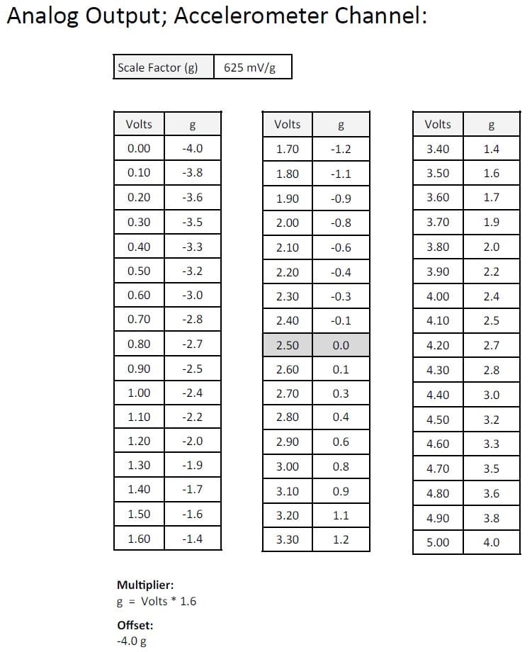
9th Output Channel: Onboard ±4g Accelerometer
The module includes a single-axis accelerometer output:
- Range: ±4g
- Scale: 625 mV/g
- 0g ≈ 2.5 V
The axis aligns with the module’s long axis. Mounting orientation determines the measured axis.
This provides a useful reference for correlating EGT data with acceleration, but is not intended to replace a dedicated multi-axis IMU.
Ungrounded Junction Requirement
All thermocouples must use ungrounded junctions.
Grounded probes create multiple electrical paths through the chassis, producing offsets caused by ground potential differences. These offsets appear indistinguishable from real temperature differences.
Ungrounded probes isolate the sensing junction and eliminate this issue.
Input Protection
- Maximum input bias voltage: 5.8 VDC
This is a protection limit, not a normal operating condition. It becomes relevant only in fault conditions such as wiring damage or unintended voltage contact.
Wiring
Output Harness
- 12-conductor detachable cable
- 8 thermocouple outputs
- 1 accelerometer output
- 1 common ground
- 2 power leads
Power
- 10–32 VDC
- <50 mA
Thermocouple Inputs
- Mini thermocouple connectors
- Type K polarity:
- Yellow = Positive (+)
- Red = Negative (–)
Correct polarity must be maintained.
Mounting and Environment
- Dimensions: 7.0" × 3.5" × 1.6"
- Protection: IP51
- Operating temperature: 32–125°F
Install in a protected environment such as a dashboard, enclosure, or cabin-mounted electronics panel. Avoid direct exposure to heat, spray, or vibration sources.
Technical Specifications
| Parameter | Specification |
|---|---|
| Inputs | 8 Type K thermocouples |
| Outputs | 8 analog + 1 accelerometer |
| Output Range | 0–5 VDC |
| Scale | 2.2 mV/°F |
| Non-linearity | < ±2% FRO |
| Input Resistance | 60 kΩ |
| Supply Voltage | 10–32 VDC |
| Current Draw | <50 mA |
| Operating Temp | 32–125°F |
| Protection | IP51 |
| Origin | USA |
Applications
- Motorsport DAQ systems (per-cylinder EGT logging)
- ECU integration for EGT-based control strategies
- Engine dyno instrumentation
- Experimental aircraft systems
- R&D and data acquisition environments
Summary
The TCA-MS-K-8-A4 provides multi-channel thermocouple signal conditioning for systems requiring analog voltage outputs.
- Converts thermocouple signals to usable voltage
- Enables synchronized multi-channel EGT logging
- Integrates directly with DAQ and ECU systems
- Includes onboard accelerometer for additional context